Choose your Link: what connects where, which programs to keep running and how to check that data has reached the site.
The server distinguishes between a connected device and incoming data. Once your Link is recognized, check the current frequency and the time of the latest decode. Saved old decodes do not confirm current reception.
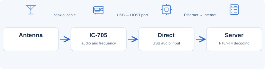
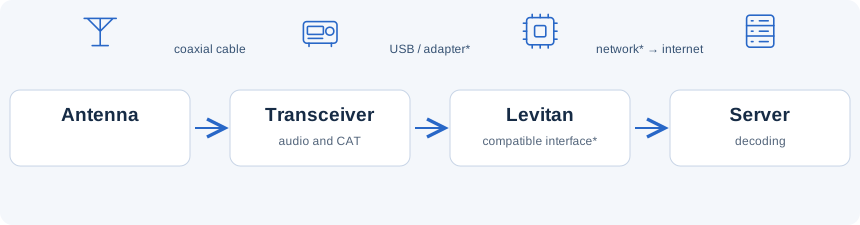
Antenna → IC-705. Transceiver USB → Direct USB HOST. Direct Ethernet → router. Power the board.
2. Start
Standalone reception needs neither a computer nor WSJT-X. Enable “Node” mode on the site if decodes should be published in the shared live activity.
3. Check
The site recognizes Direct → a current frequency appears → audio arrives → new decodes are published.
“Operator” mode and node publication are separate states. Connecting the board alone does not enable publication. The verified network path is Ethernet.
Prototype · needs hardware testing
Link + Digirig
For older transceivers without USB
Digirig adds a USB audio interface to older radios without built-in USB. CAT is available when supported by the radio and matched cables/configuration.
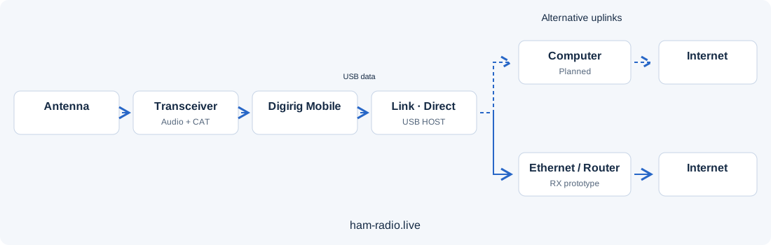
Antenna → transceiver → Digirig → Link USB HOST. Use audio and CAT cables made for your radio and the matching Digirig CAT configuration.
2. Start
From the Link: computer → Internet, or Ethernet → router → Internet. These are alternative uplink paths.
3. Check
Check device recognition, received audio and current frequency first; then check fresh decodes on the site.
The Digirig + Direct firmware is an RX prototype awaiting hardware tests. Its current implementation uses Ethernet; the computer uplink is planned. Transmission and PTT are not verified. Digirig Mobile ↗
Verified · NESDR + P4
SDR Link
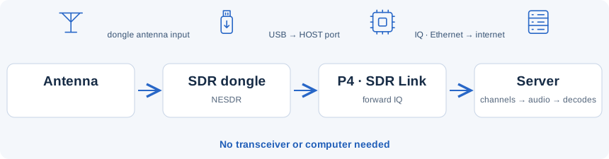
No transceiver needed · IQ from the SDR dongle reaches the server
The target mode uses no computer and no WSJT-X. This is a requirement for a future Link, not a verified feature of the current firmware.
3. Check
Once implemented, board recognition, frequency, audio stream and decode publication will need checking.
* The exact cables, USB HOST, power and AtomS3 Lite network profile still need verification. Do not connect a transceiver using this setup as if it were a ready-to-use Direct.
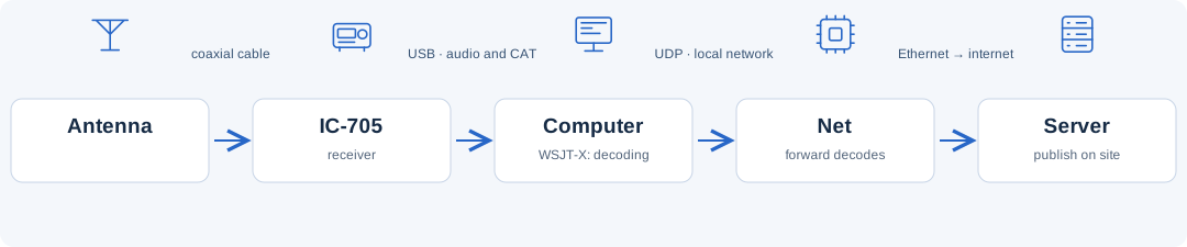
Computer: Required continuouslyDecoding: On the computer for WSJT-X
1. Connect
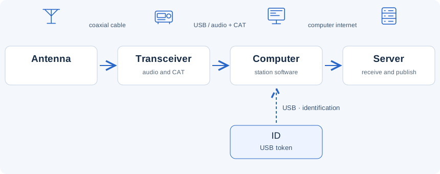
Transceiver → computer using your working setup. ESP32-C6 → a separate USB port on the same computer.
2. Start
A computer and Link Service are required. For ready-made decodes, start WSJT-X; for another source, start the corresponding program.
3. Check
Link Service recognizes the token → the server confirms the node → frequency and incoming radio data are checked separately.
Here ESP32-C6 is only an identification token. It carries no audio, IQ or decodes and does not replace the computer’s internet connection. The token verification mechanism still needs checking.